
We came across an interesting observation while designing surge volume calculations in flotools that I thought was worth sharing and inviting comments from the flow assurance community. For those that are not 100% sure what surge volume is exactly, let me first explain.
Calculating surge volumes is a routine part of a flow assurance engineer’s work. Operational scenarios like slugging, pigging, production ramp-up in multiphase production systems can all result in large volumes of liquids being swept out of the pipeline and into the first vessel on the receiving facility. Often, these liquid surges come in at rates that far exceed the receiving facility’s capacity to process liquids. Therefore the vessel, typically a slug catcher, acts as a buffer where the surge of liquid can be collected and processed over time. One of the objectives of performing flow assurance studies is to quantify the maximum surge of liquid that can be seen across various operations in order to size the slug catcher appropriately. The maximum volume that a slug catcher will have to hold for a given operation is called the surge volume.
OLGA provides a way to calculate surge volumes whenever at least one of ACCLIQ, ACCOIQ, and ACCWAQ is included in the list of trended outputs. The calculation assumes that the slug catcher is present just downstream of the location where these variables are trended and that the vessel can be drained at a fixed maximum drain rate during the operation.
The calculation performed by OLGA is described by the following equation:
[1]
[2]%5Cbigg)%7D)
[3]%7D%5C%3A%5Ctext%7B%20where%20%7D%5C%3AT_%7Bend%7D%5Cleq%20t%5Cleq%20T_%7Bend%7D%0A)
where
 is the OLGA reported cumulative volume of liquid at time step
  ,
,
 is the elapsed simulation time at time step ,
 is the maximum drain rate of the slug catcher,
 and
and  mark the time window in the simulation where the calculation is done, and
 is the calculated surge volume
In this post I will look at two interesting properties of this calculation:
- Why were the accumulation variables (ACC*) used instead of the instantaneous rate variables (QL*)?
- Why is there a
 operation in equation (2)?
%7D) operation in equation (2)?
operation in equation (2)?Accumulation Variables vs. Instantaneous Rate Variables
OLGA’s calculation of surge volume uses the accumulated variables as the basis of the surge volume calculation instead of the instantaneous liquid volume rate variables (QLT, QLTHL, QLTWT). To understand why, let’s look at the instantaneous rate form of the surge volume equation.
When using the instantaneous rate variables, equation (2) becomes,
[4]-Q_%7Bdrain%7D%5Cbigg)%5Ccdot%20(T_%7Bt%2B1%7D-T_t)%5CBigg)%7D)
If we compare the accumulation terms from (2) and (4), we see the following assumed relationship:
[5]%5Ccdot%20(T_%7Bt%2B1%7D-T_t))
In other words, the average of the instantaneous rates in a particular time window is approximately equal to the average accumulation rate in that time window. This is typically a bad assumption because the instantaneous rates capture rate spikes that are very short in duration and would not be indicative of the average rate for the corresponding time window. The average rate can be calculated as follows:
[6]
The following chart shows a comparison between an actual QLT output from OLGA and the associated average QLT calculated from ACCLIQ according to equation (6):
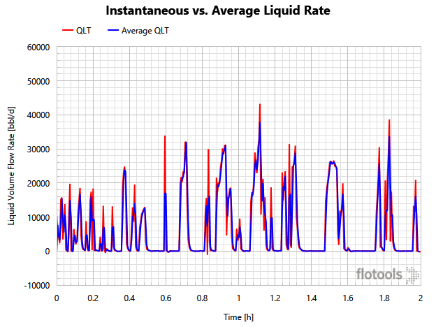
You can see that the average QLT (from ACCLIQ) does not show the flowrate spikes that the QLT variable shows. These spikes, while they probably do occur in a flowing system, typically occur in very short time windows smaller than the output interval of the simulation. The larger the output interval, the worse the assumption.
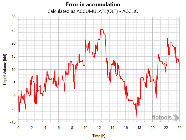
The following chart shows an example of the error in accumulation by comparing the calculated accumulation using the rate variable and subtracting the OLGA calculated ACC variable from it. While the maximum error in this example (~25 barrels) is not significant, the magnitude of the error entirely depends on the nature of the simulation and may be significant in some cases.
In our view, OLGA has taken the correct approach and used the accumulated variables as the basis for the surge volume calculation.
Handling Negative Terms
Equation (2) features a  operation. This ensures that the calculated volume in the slug catcher never goes below zero. But what happens when the quantity
 ) becomes negative?
becomes negative?
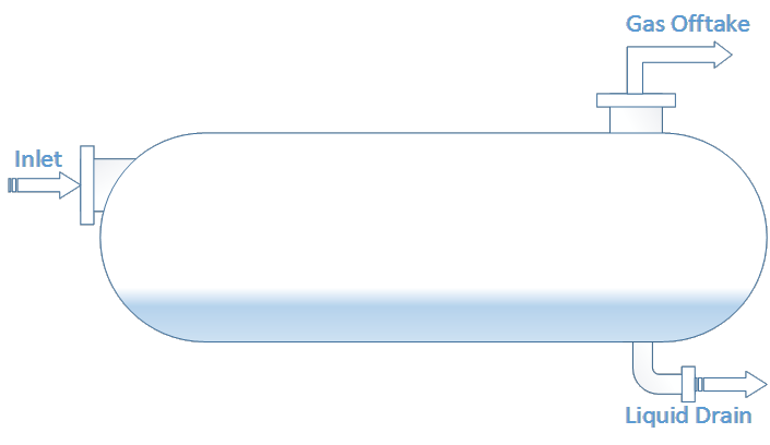
It is perfectly normal and valid for a numerical simulator to predict negative rates at an outlet boundary. When OLGA predicts negative rates at the outlet of the pipeline, the ACC variable may reduce in value from one time step to the next. When this happens, equation (2) will result in a reduction in the calculated slug catcher volume at a rate faster than the assumed drain rate. Effectively, the calculation does not prevent the possibility that liquid can leave via liquid drain as well as the inlet of the slug catcher. When you look at a schematic of a typical slug catcher, like the one shown below, it becomes apparent that this may not be such a sound assumption. The slug catchers are designed for gravity separation of phases and hence the inlet nozzles are at or near the top of the vessel. Once the liquids go in, they quickly settle to the bottom. Any negative flow is likely to be mostly gas with very little liquid carried as droplets in the gas phase.
Depending on your case, using the OLGA basis for calculation may result in significant errors. In one case, we found a 10% error at a specific drain rate. The problem is that the error is not on the side of conservatism. We think the correct way to write equation (2) is as follows:
[7]%7D-Q_%7Bdrain%7D%5Ccdot(T_%7Bt%2B1%7D-T_t)%5Cbigg)%7D)
In equation (7), we added another max function that bounds the quantity , which is the average flow rate into the slug catcher for a given time interval, to zero.
If the calculation is being done at the outlet of a pipeline that is connected to a pressure node, set the parameter GASFRACTION to 1.0 in your NODE specification. This will ensure that whenever there is negative flow at the outlet boundary, the negative flow is all gas. That said, we still think equation (7) is a better way to perform the surge volume calculation because it works well regardless of the boundary specification.
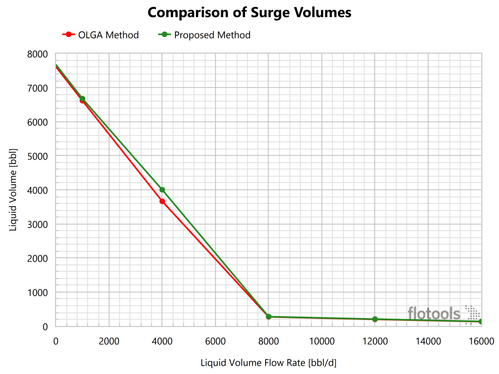
The plot above shows a comparison of surge volumes calculated according to equations (2) and (7), labeled “OLGA Method” and “Proposed Method” respectively. We can see that filtering out the negative values results in larger surge volumes at lower drain rates. At large enough drain rates, the differences eventually disappear. Given surge volume calculations are performed in order to size the slug catcher, we believe that equation (2) is not conservative and therefore should not be used. Instead, our modified version represented in equation (7), which gives a more conservative estimate of surge volume, should be used.
As always, your comments and feedback would be much appreciated.
Great post. Did you guys run the comparison with boundary [GASFRACTION] set to 1? I would like to know how it plots or compares. Let me know. Thanks.
Maria, thanks for your question. Unfortunately, we did not run a case with GASFRACTION set to 1.0. Theoretically though, doing that should prevent ACCLIQ from reducing in value from one time step to another. Under that condition, our modification to the equation becomes unnecessary.
Great article, makes a lot of sense.