Problem Statement
Decarbonization has become a politicized issue in recent years. As engineers our mandate is to examine problems and provide solutions, not necessarily to pontificate on the validity of the problems posed or the priorities that should be placed on these problems. In this blog post, we will examine said problems and discuss methodologies to arrive at solutions. A full technical description of this work is available in the paper PSIG 2216.
One such solution is increasing the use of hydrogen (H2) as a fuel source. Is H2 the hero that we have been waiting for to cancel carbon and lead us to a bright future? Maybe. But it will take a lot of smart work and human ingenuity to cross the “carbon chasm”. H2 will need help to become the super-hero that saves the day, year, millennium…
Engineers, like most humans, tend to be negative as the cost of failure often outweighs benefits. But let’s put our pessimism aside and look at some of the positive aspects of hydrogen as an additive to existing fuel streams.
- Hydrogen fuel consumption produces no carbon dioxide (CO2)
- There are vast existing networks of natural gas pipelines and processing infrastructure
So that is the good, let’s take a look at the bad (and ugly). While our heroic H2 is not the villainous carbon, it is also perhaps not the workhorse that modern society has come to rely on. Actually, H2 poses some new problems to consider. These include;
- Reduction in transportation efficiency
- Hydrogen embrittlement of steel
- Change in combustion effects
- Eventual separation of hydrogen from natural gas
- Changes in pipeline operations
Addressing these problems requires a methodical analysis of the systems involved. An overarching question one may begin with would be, how to start to characterize and understand the impacts of a hydrogen-rich gas stream? A comparison of the accuracy of various equations of state (EoS) for modelling fluids containing H2 would be a good start. Ultimately, it would be useful to quantify the impact of increasing the H2 content to the hydraulics of natural gas systems. We should examine steady state scenarios, such as the line capacity. Additionally, we should examine transient operations, such as linepack.
Equation of State Investigation
To evaluate the feasibility of hydrogen utilization a high-accuracy EoS is crucial. Perhaps the most impactful fluid property from a hydraulic perspective is density. To better understand the accuracy of various EoS, we will compare density predictions to measured data.
The Hernandez-Gomez [1] et al data set from 2018 measured the density of methane-hydrogen binary mixtures over a range of compositions, pressures, and temperatures relevant to transport of H2 in natural gas pipelines.
The best known and most widely used EoS is that of Peng-Robinson (PR) from 1973. PR is a cubic EoS, which makes the job of coding up this EoS in simulators easy for software developers but does not provide the best physical description of fluids. More modern takes on EoS are complex models such as Groupe Européen de Recherches Gazières (GERG) 2008 and American Gas Association (AGA) 8. It should be noted that AGA8D is a composition-based method for predicting fluid properties, while AGA8P utilizes bulk properties of the gas to predict fluid properties. AGA8P utilized CO2 content, specific gravity, and heat content as inputs, while AGA8D uses a more detailed approach.
Gas densities predictions from GERG, AGA8, and PR EoS are compared to the measured data from Hernandez-Gomez 2018 in Figures 1-3.
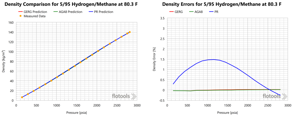
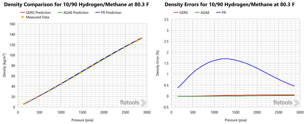
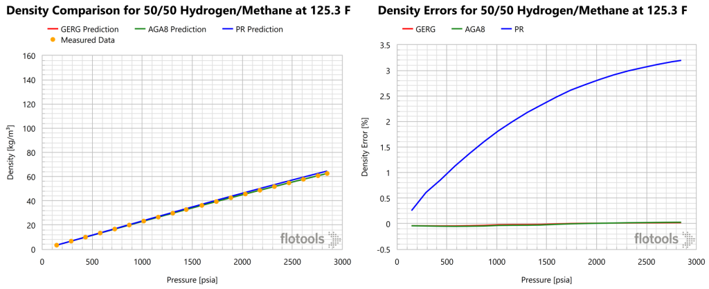
From the figures above we noted that while PR may be acceptable for quick screenings, the error is larger than should be acceptable for a realistic analysis of natural gas systems. GERG or AGA8 are recommended for modelling hydrogen blends in transport and processing. Furthermore, the error or PR increases with increased H2 concentration. It should be noted that the figures above were generated using the Multiflash thermodynamic simulation software, which does not support the AGA8P EoS. Thus, AGA8D was used for this analysis. Results for AGA8P would be expected to be worse than those of AGA8D. A summary of the findings from Figure 1, Figure 2 and Figure 3 are provided in Table 1.
| H2 content (mol%) | Average Error (%) | Average Absolute Error (%) | ||||
|---|---|---|---|---|---|---|
| GERG | AGA8D | PR | GERG | AGA8D | PR | |
| 5 | 0.02 | 0.00 | 0.58 | 0.03 | 0.03 | 1.08 |
| 10 | 0.03 | 0.00 | 1.06 | 0.05 | 0.04 | 1.17 |
| 50 | 0.00 | -0.02 | 2.70 | 0.04 | 0.03 | 2.70 |
Hydraulic Model Basis and Steady State Analysis
As many of us learned at some point in our academic or professional careers; all models are wrong, but some are useful. In order to analyze cases on a like for like basis, special care must be taken when asking, “compared to what?”. For this analysis we aimed at modelling a real-life system as a basis, and then creating comparison cases where flow rate was equivalent but H2 content increased, and where the total caloric value of the fluid was held constant while the H2 content increased (equivalent energy).
The system in question was a pipeline with three compression stations spaced more or less equidistantly between the inlet and outlet. This pipeline system included multiple parallel pipelines, with several delivery points along the lines. An idealized schematic is given in Figure 4.

Each compressor station had a minimum suction pressure of 500 psig. The compressor station nearest to the inlet (Station A) had a discharge pressor that varied below the maximum allowable operating pressure (MAOP). The middle station (Station B) had a discharge pressure controller that was set at 894 psig. The station closest to the outlet (Station C) had a discharge pressure controller that was set at 936 psig.
The composition was varied with H2 at a baseline value of 0.02 mol%, then additional cases were considered with 5, 10 and 20 mol% H2, while the concentration of other components was held in proportion to the baseline case. This resulted in the gas compositions considered for this analysis, given in Table 2.
| Component | Fluid 1 | Fluid 2 | Fluid 3 | Fluid 4 |
|---|---|---|---|---|
| Mol% | ||||
| CO2 | 0.30 | 0.29 | 0.27 | 0.24 |
| He | 0.00 | 0.00 | 0.00 | 0.00 |
| H2 | 0.02 | 5.00 | 10.00 | 20.00 |
| H2O | 0.00 | 0.00 | 0.00 | 0.00 |
| H2S | 0.00 | 0.00 | 0.00 | 0.00 |
| N2 | 0.50 | 0.48 | 0.45 | 0.40 |
| O2 | 0.01 | 0.01 | 0.01 | 0.01 |
| C1 | 94.70 | 89.98 | 85.25 | 75.78 |
| C2 | 4.20 | 3.99 | 3.78 | 3.36 |
| C3 | 0.20 | 0.19 | 0.18 | 0.16 |
| iC4 | 0.02 | 0.02 | 0.02 | 0.02 |
| nC4 | 0.02 | 0.02 | 0.02 | 0.02 |
| iC5 | 0.01 | 0.01 | 0.01 | 0.01 |
| nC5 | 0.01 | 0.01 | 0.01 | 0.01 |
| nC6 | 0.01 | 0.01 | 0.01 | 0.01 |
Steady state simulations were run as a parametric study to investigate the total power usage and suction pressures for the system. This study included an analysis of 32 cases with the parameter variations given in Table 3.
| Parameters | Conditions | Variations |
| Equation of State | AGA8P AGA8D Peng-Robinson (PR) Benedict Webb Rubin Starling (BWRS) | 4 |
| H2 Content | 0.02% (base) 5% 10% 20% | 4 |
| Equivalence | Flow Rates Maintained Energy Maintained | 2 |
Before jumping to findings, we should clarify why two flowrates were considered for this analysis. This speaks to one of the challenges with H2 as an energy source, namely that H2 is less energy dense than natural gas. The result is that to maintain demand on a like for like basis, i.e., to keep customers happy, higher overall flowrates are required as H2 content increases. This poses another question, “will the H2 rich fluid flowing at or below MAOP provide sufficient energy to meet demand”? If so, what would be the added operational cost for compression, i.e., power requirements, as H2 content increases?
Power requirements for compression stations A, B, and C were calculated for the four fluid compositions and several EoS considered in this analysis. It should be noted that the simulator used for these scenarios included options for AGA8D and AGA8P, along with the more rigorous Benedict-Webb-Rubin-Starling (BWRS) EoS. Power requirements for each station as a function of H2 content with various EoS are depicted in Figure 5.

The AGA8P results are inconsistent. The overarching trend was a decrease in power usage as H2 content increased. The power usage for Stations A and C are essentially constant (note the scales on the y-axis are not the same), while that of Station B was responsible for the overall inverse relationship for the system. This was the expected result, as pressure drop was expected to decrease with increasing H2 content as the volumetric flowrate remained unchanged.
The suction pressures at each station are provided in Figure 6 as a function of H2 content.

This is the result one would expect with the lower pressure drop discussed above with increased H2 content. As in the previous charts, the AGA8P results are inconsistent, and are considered to be erroneous compared with those of the more rigorous models.
An analysis of this system with the volumetric flowrate held constant would be only part of the picture. The customer’s concern is with their energy demand, not so much with the volume of gas required to deliver said energy. For this reason we evaluated cases whereby the total caloric content of the gas stream was equivalent to that of natural gas. Due to the lower energy density of H2, a greater volume of gas would be required to deliver equivalent energy to customers. The power usages and suction pressures are given in Figure 7 and Figure 8, respectively.


Under equivalent energy conditions, the power usage for Stations A and B are nearly constant, while Station C required a significant increase in power as H2 content increased. The power requirements of Station C are eventually constrained by the minimum suction pressure requirement. In fact, the Station C discharge pressure was not able to be maintained under these conditions. The limiting factor at high H2 content is the minimum suction pressure, which was maintained at 500 psig, and constrained the power usage. Station B saw decreasing suction pressure with increasing H2 content, as power and minimum suction pressure constraints drove the response. For Station A, power was the limiting constraint.
Transient Analysis
A key factor for operability of a natural gas asset is the degree to which the volume of the system can be leveraged to safely compress fluids for a brief time, and then later utilized. Adding H2 to natural gas fluids tended to increase the mass of gas that could be packed into the pipeline while the outlet boundary was closed.
Linepack transient simulations were run from initial conditions or each of the steady state simulations (4 EoS x 4 compositions = 16 cases). However, due to the low accuracy of PR and AGA8P only results for AGA8D and BWRS EoS will be discussed. The linepack scenarios assumed a real consumption profile (from actual field data) with a constant inlet flowrate. Simulations were run for 24 hours under these conditions. Results for simulations with the inlet flowrate for all compositions held equal are provided in Figure 9.
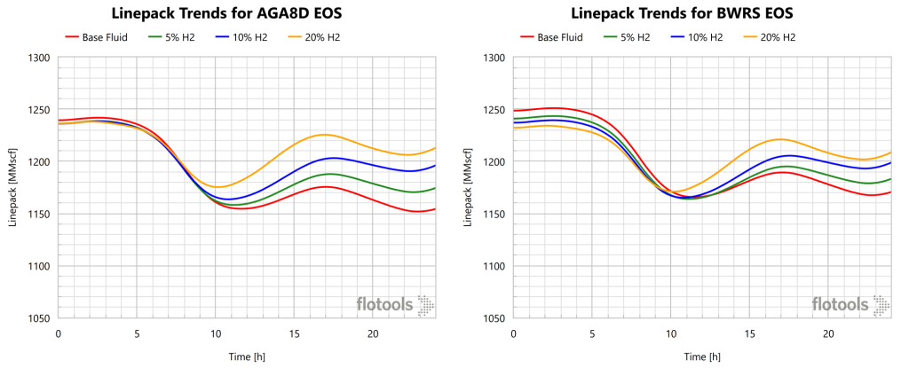
The important findings from these results are that the BWRS and AGA8D EoS produce outputs of similar tendencies, albeit varying magnitudes. Additionally, linepack increases as H2 content increase. This means that adding H2 to the natural gas fluid actually increases the operability of the system.
As in the steady state analysis, we must ultimately ensure that the customer’s demands are met; thus, the more relevant results are of the scenario whereby equivalent energy is delivered. These scenarios were also simulated, with the flowrate adjusted to result in an equivalent amount of energy entering the pipeline system during linepack. Given the approximate similarity of AGA8D and BWRS EoS results, we shall only examine the AGA8D results in Figure 10.
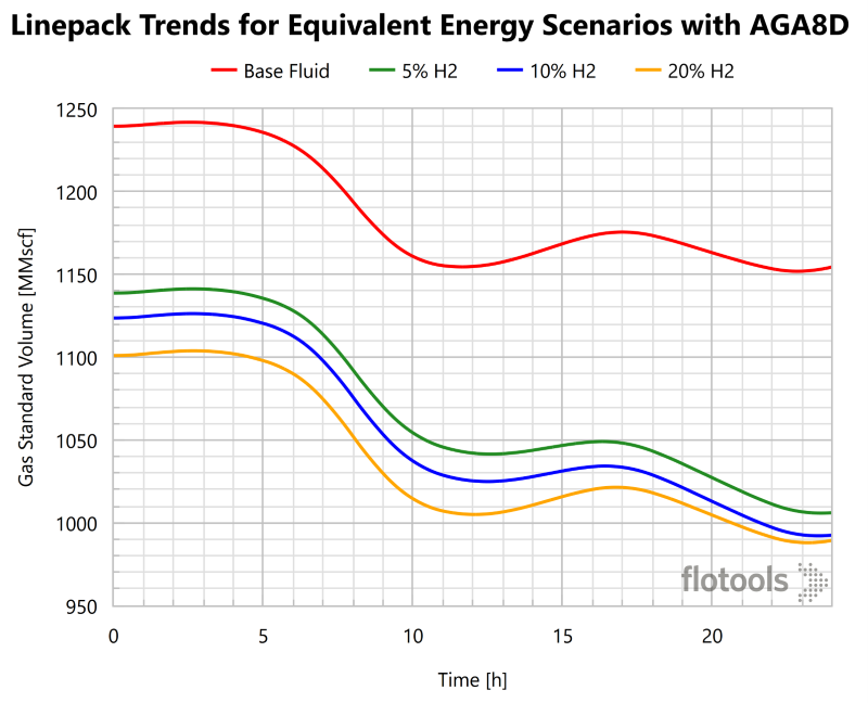
Contrary to the equivalent flowrate case, with equivalent energy inflow we observe decreased linepack with increased H2 content. This means that on an energy delivery equivalency basis that the pipeline system has less operational flexibility when H2 is present. In comparing linepack of the base case natural gas composition to that of the highest H2 content (20 mol% H2) the change in linepack was greater when greater H2 content was present. In this case the linepack difference (initial – final) was 29% greater for the highest H2 content as compared to the base case. The reason for decreased linepack is that to maintain equivalent energy content additional mass must be added, as H2 is less energy dense than hydrocarbon gases.
Next Steps and Conclusions
To summarize findings from the three studies that were conducted (EoS comparison, steady state power usage and hydraulic analysis, transient line pack analysis) we will now mention a few key takeaways.
EoS Formulation Conclusions
- GERG and AGA8D rendered extremely high accuracy in gas density predictions as compared to measurements. Accuracy of the BWRS EoS was slightly less, but still within the bounds of acceptability.
- Results from using the AGA8P EoS were erratic. Linepack was over-predicted for some mixtures, while under-predicted for others.
- PR consistently over-predicted gas densities, leading to excessive linepack predictions. Comparable results would be expected from other cubic EoS. Thus, PR and its cubic brethren are not recommended for such analyses.
Steady State Analysis Conclusions
- H2 decreases pressure drop and power usage for the same flow rate.
- This comes at a “cost” of less energy for equivalent flowrates. When considering equivalent energy H2 increases pressure drop and power usage requirements.
Transient Analysis Conclusions
- The decreased pressure drop associated with increased H2 content on an equivalent flowrate basis results in greater linepack and more flexibility in operations.
- When equivalent energy content is assumed, H2 decrease linepack.
Next Steps
This line of inquiry will be of increasing importance as the industry moves toward hydrocarbon alternatives. Additional research and investigation will be required to better understand the viability of H2 as a fuel source or additive. The smaller molecular size of H2 poses containment issues that must be addressed from an operational and material science basis.
Topics for further investigation include, pigging, leak detection and depressurization operations. Additionally, it would be useful to better understand burn tip efficiency, process equipment requirements, storage requirements, reservoir-fluid interactions, and metallurgy issues for increased H2 fluid streams.
Will H2 be our gallant champion, a dragon to be slain, or a complex mixture of both that can be harnessed? If nature provides free lunches, it does not send invitations our way often. Tackling de-carbonization is no different. It will require significant amounts of additional work to be viable, but the value of reaching a hydrogen powered future is certainly worth further investment.
- Hernandez-Gomez, R.; Tuma, D.; Perez, E.; and Chamorro, C. R. “Accurate Experimental (P, rho, and T) Data for the Introduction of Hydrogen into the Natural Gas Grid (II): Thermodynamic Characterization of the Methane-Hydrogen Binary System from 240 to 350 K and Pressures up to 20 MPa.” J. Chem. Eng. Data 2018, 63, 1613-1630

Hi there,
Great job. Thanks for sharing this valuable topic. Here are three questions I am willing to have your invaluable comments and would be appreciated it:
1- The first point is adjusting an EOS to build the fluid model. I was wondering bout these experimental data. Moreover H2 behaviour and real data in binary vs multicomponent systems.
2- The second point is the relative devotion of the results in comparison with the field data when you use the BWRS rather than the other EOSs.
3- The final point is the chemical reaction equilibrium contribution for H2-Rock-Brine-Natural Gas (residual oil/condensate) relative to thermodynamic physical equilibrium. How much, do we need to deal with the chemical reaction equilibrium?
Hi Sam, thank you for the comment! Great questions! Here are our responses;
1) Modern EoS are fit almost entirely with pure component and binary data. Multicomponent data are used primarily as an independent check. I’m not aware of any EoS that utilizes multicomponent interactions. Multicomponent data can be used to tune an EoS, but only the binary interactions are being tuned. So, the binary data should be sufficient. This is particularly the case for the application discussed in the blog post since methane and hydrogen will make up the vast majority of the mixture. Components present in small amounts are mainly important for phase boundaries, but that is a separate topic.
2) We concluded that BWRS is acceptable (it gives consistent results of sufficient accuracy for engineering work), but it is less accurate than GERG and AGA8D.
3) I don’t think chemical equilibria is an issue for natural gas transmission with hydrogen since there is no oxygen/brine in the mixture. Obviously, there are other applications where this a relevant concern.